Hints and Tips
Also visit the LDSIG’s Glossary of Layout Design Terms
Contents
- Blocks
- Classification Yards
- Practical Yard Design Example
- Curve Radius Rule-of-Thumb
- Curves
- Easyspline Masonite Roadbed
- Sanborn Maps
- Timeline-Freight Cars
- Train Length and Layout Design
- Uncoupling Methods
- Vertical Curves
Blocks
A “Block” is a group of cars that will be handled together from a location to the next place the cars are classified, interchanged, change trains, or spotted at an industry. The cars may be different final destinations. Blocks may be differentiated by:
- Final destination
- Interchange road
- Next switching location
- Car Type
- Industry
- Direction
- Next train
Blocks are identified by a block name or code:
- Text name (Houston)
- Alphanumeric code (HOU1)
- Numeric code (135)
Blocks are used in classification yards to separate the cars. Each classification track may hold one or two blocks. Blocks are also used to assemble trains, a particular train symbol or schedule will carry only certain blocks. The blocking pattern is described in a “transportation plan” for the train. One special type of blocking, particularly used on locals, is station order blocking. The cars are blocked by the destination station, and the train is assembled with the blocks in order from the front of the train to the rear of the train in the same order the train will arrive at the stations. So if a train originates at Anna and operates on the route Anna-Bess-Cloy-Dora-Eve-Fay, the train will be blocked:
Caboose-Fay-Eve-Dora-Cloy-Bess-Engines
It is also possible, that a train such as the one above may be blocked in reverse manner as follows:
Caboose-Bess-Cloy-Dora-Eve-Fay-Engines
This will more likely be trains that run over several sub-divisions where the blocks will be added and removed at crew change points by yard switchers.
Classification Yards
Classification yards are arrangements of tracks used to sort or classify cars. They receive inbound trains or cuts of cars, and switch them according to their outbound blocks, and build them into outbound trains.
Large yards may have sub-yards separated by function.
Arrival/Departure yard/tracks: Longer tracks designed to receive an inbound train or cut or tracks in which an outbound is built. Large yards may have separate Arrival and Departure yards.
Classification yard/tracks: Shorter tracks used to sort or classify cars by outbound block.
City yard: Small yard used to hold local industry cars.
RIP tracks: Tracks where cars are repaired (Repair In Place).
Caboose tracks: Tracks used to hold cabooses between trains, where they can be cleaned and serviced (fuel, ice, water, supplies, etc.).
Switching lead: Track dedicated for use by the switch engine while classifying cars. Gives the switcher tail room (room to pull back) while switching.
Scale track: Track with a scale on it to weigh cars for billing purposes.
Practical Yard Design Example
Guy Cantwell has been kind enough to provide a copy of his thoughts and actions in building a small yard on his layout. Please see the attached file for his work: Willoughby Yard Design.doc.pdf (890.49 KB).
Curve Radius Rule-of-Thumb
Here are some curve radius guidelines based on the lengths of your longest pieces of rolling stock.
2X: Some model equipment may be able to track reliably on 2X their length, but this is generally considered pushing it.
3X: Making your curve radius at least 3X the length of your longest cars gets reliable tracking around curves, but looks toylike.
4X: If you can make your curve at least 4X, your longest cars will look much better on curves.
5X: If you make your curve radius at least 5X, your longest cars will couple easily with minimal manual fiddling of the couplers.
This measurement is based on the length of your longest car (coupler to coupler).
HO Examples
For example, an HO forty foot boxcar is about 6″ long, coupler to coupler. Here are the curve radius guidelines if your longest cars are forty footers:
FORTY FOOT CARS
Curve Radius: 2X – 12″; 3X – 18″; 4X – 24″; 5X – 30″
If you go below 18″ radius, your cars may not track well on curves, although some equipment may still track okay down to 12″ radius. You need at least 24″ radius for your cars to not look toy-like on curves. To have reliable coupling on curves, you need a 30″ radius, which would be a good minimum radius standard for a yard on a curve, for example.
However, few will only have forty foot cars as the longest cars on their layouts. Here are some guidelines in HO for other more common “longest” car lengths:
FIFTY FOOT CARS
Curve radius: 2X – 15″; 3X – 22.5″; 4X – 30″; 5X – 37.5″
SIXTY FOOT CARS
Curve radius: 2X – 18″; 3X – 27″; 4X – 36″; 5X – 45″
EIGHTY FOOT CARS
Curve radius: 2X – 24″; 3X – 36″; 4X – 48″; 5X – 60″
So to summarize, some cars or locos may track okay at 2X, but at 3X cars of that length will all track well, use 4X if you want things to look decent, and use 5X if you want reliable coupling on curves (like say a yard on a curve).
Further Comments
Here’s another trick you can take advantage of, too. Curves, when viewed from the inside, don’t look as sharp. So for inside curves, you can drop the radius to 3.5X instead of say 4X (say 27″ instead of 30″ for 50-foot equipment) and the curve will still look pretty good.
But outside curves (like at the end of a peninsula) look sharp and the equipment doesn’t look as good, so the curves there should be as broad as possible. If you can manage it, you should use the 4X rule (at least) for those curves.
If all the cars are similar length, you can drop to perhaps 2.5X, but if you have a mix of longer and shorter cars, you’d better go at least 3X of the longer equipment if you don’t want tracking problems, or 5X of your longest equipment if you want the most reliable coupling. Widening the gauge to maximum may help with ridged wheelbase steam locos.
You may be also able to do 3X on longer equipment and get reasonable coupler performance if the couplers have been altered to allow them to swivel at least 50% of the width of the car.
To be absolutely sure what works best with your equipment, do some testing on your own, using these guidelines as a starting point.
Curves
Prototype railroads in North America measure curves by degree of curvature, not radius. The degree of curvature is measured by in the field by the offset of a 100 foot chord.
For a prototype curve:
R = Radius of the curve
D = Degree of curvature
R = 50 / sin(D/2)
So for a 4 degree 30 minute curve:
R = 50 / sin(4 deg 30 min/2)
R = 50 / sin(2 deg 15 min)
R = 50 / 0.0392
R = 1275 feet
To convert to HO radius in inches:
Rho = (R / 87) x 12
Rho = (1275 / 87) x 12
Rho = (14.655) x 12
Rho = 175 inches
Typical mainline curves are in the 2 to 6 degree range. Sharp curves those above 10 degrees.
UNITED KINGDOM
In the United Kingdom and most countries that belonged to the former British Empire, prototype curves are commonly measured by radius. In pre-metric times, the radius was often measured in chains.
1 chain = 22 yards = 66 feet
Easyspline Masonite Roadbed
When I started in this hobby I used Woodland Scenics foam roadbed, but after reading Joe Fugate’s Easyspline Masonite roadbed, I decided to try it out, and WOW, what a difference.
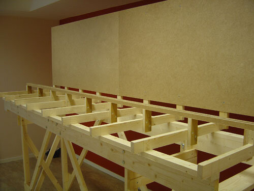
I started by adding my risers made from 1 by 2.
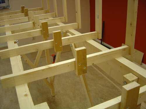
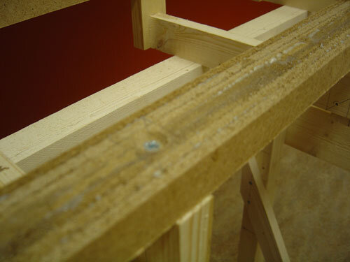
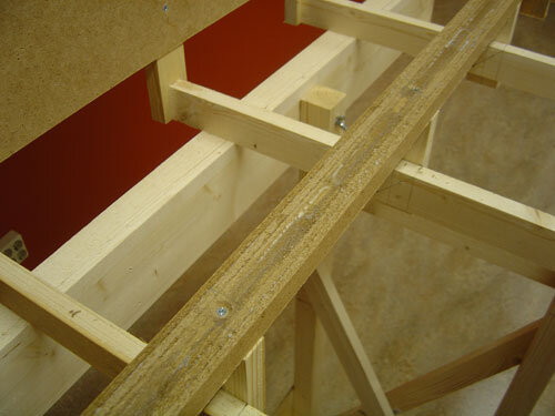
I got the Masonite splines from a local carpenter. They are made from 1/4″ Masonite and around 20mm in height. Next time I will try to make these splines myself because I’m not 100% satisfied with the carpenter. I think it is important to have the same size for all splines. In my case some are 20mm, others are 22 and 21.
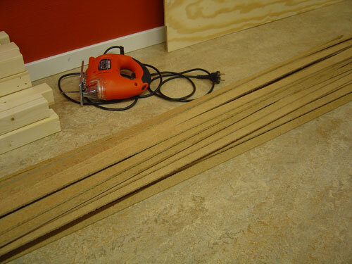
I laminated 7 splines together to make the roadbed 42mm wide (7 x 6). I used lots of spring clamps to hold them in place while the glue dried overnight.
Here are some closeup pictures of the finishing roadbed. Use a Surform plane (I used one from Stanley) to take away the glue on the top and to make the roadbed smooth.
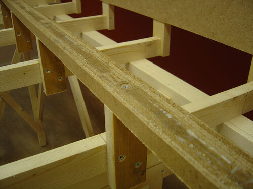
Next step is to glue the track directly to the roadbed with latex caulk. If you have gray ballast, use gray caulk.
Why do I like this method?
– I think this method is the best you can use for roadbed, and I will never go back to any other method, never.
– It’s easy to make curves and grades, and it’s VERY sturdy.
– And you can use it for any scale, just laminate splines until you have the right size.
Try it out, I am sure you will like it. Thanks to Joe Fugate for showing me this roadbed construction method.
(And thanks to Lee Nicholas for showing it to me — Joef)
Sanborn Map
Sanborn Insurance Maps were made of 12,000 cities and towns across the United States by the Sanborn Map Company beginning in 1867 for the purpose of assessing fire risk and setting insurance rates, and they were the primary American publisher of fire insurance maps for nearly 100 years. They include not only moderately detailed information about the location of structures, railroad tracks, and streets drawn at a scale of 1″ = 50′ 0″, but they also included the height and material of the structures, location of doors and windows, cranes and other equipment, storage tanks, use of the building, etc. An invaluable tool when researching for a model railroad, they, along with photographs, track charts, and ICC Valuation maps, can give a very accurate rending of what was happening in most any urban area of the country beginning around 1900. These maps can generally be ordered via Interlibrary Loan from your public library. Some libraries will have the maps for the local area or state on-hand in hardcopy format, and maps that are borrowed from other libraries will be generally be on microfiche or microfilm. Copies can be made for personal use.
The map below shows a part of the Bethlehem Steel Shipbuilding Yard along the Hudson River in Hoboken, NJ. The railroad tracks shown belong to the Hoboken Shore Railroad, and run out on a 600′ pier. All the different phases of shipbuilding work can be identified in the map from rigging to copper smithing to painting.
Timeline-Freight Cars
- 1883 – Safety Appliance act passed.
- 1900 – Cars required to be equipped with air brakes and knuckle couplers.
- 1911 – Safety Appliance act amended to include ladders and grabirons.
- 1928 – Wood draft sills banned from interchange.
- 1933 – Type E or F couplers required on all new cars.
- 1933 – Rotary uncoupling levers required on new or rebuilt cars.
- 1934 – AAR created from ARA.
- 1937 – AB brakes required on all new cars.
- 1937 – Geared handbrakes are required on new or rebuilt cars.
- 1938 – Billboard cars banned.
- 1940 – Arch bar trucks banned in interchange service.
- 1945 – Wood running boards outlawed on new cars.
- 1948 – Plate B adopted, maximum height of 15 ft 1 in.
- 1954 – K brakes are banned in interchange service.
- 1957 – Trucks with cast journal boxes required (Andrews type trucks banned).
- 1958 – Cast iron wheels banned on new cars.
- 1959 – Allied Full Cushion trucks banned.
- 1963 – Plate C adopted, maximum height of 15 ft 6 in.
- 1966 – Roof running boards are banned.
- 1967 – High mounted brake wheels on new cars are banned.
- 1968 – ACI labels are installed.
- 1970 – Cast iron banned in interchange.
- 1970 – No underframes over 50 years old permitted.
- 1972 – ACI labels no longer required.
- 1972 – Roller bearings required on all 6 1/2 x 11 journals.
Train Length and Layout Design
How you design your layout’s passing sidings, yard tracks, and return loops can have a major impact on train length. In this tip, we discuss briefly what the issues are.
You can have trains longer than passing sidings and yard tracks and can deal with them, although they will slow down things a lot. But a train longer than a reverse loop will not work – – the law of physics says two objects cannot occur the same space at the same time – so the front of your too-long-for-the-reverse-loop train will collide with the back of the train once it reaches the end of the loop!
With passing sidings, the key is opposing trains. As long as one of the two opposing trains will fit, other train can be of any length – you can get the trains past each other with a bit of advanced planning. But if both trains are too long for the siding, you will need to do a double sawby maneuver. Such a maneuver is fun once in a while, but it would get old if it was standard operating procedure. This means passing siding length has a major impact on train length if you want opposing traffic to flow smoothly.
With visible yards on the layout, a too-long train can always “double the yard”, which means you split the train in two and it takes two yard tracks. This practice is not uncommon on the prototype, so it could be an acceptable operating procedure as long as you are aware that it will slow down yard operation somewhat.
Finally, too-short staging tracks can be a problem, since it will make you “double the yard” in staging as well. Requiring trains to do this in a visible yard on the layout is one thing, but requiring this in staging is going to get old, so the recommendation is don’t. Staging track length has a major influence on train length.
MORE INFORMATION
Layout design analysis article on Joe Fugate’s Siskiyou Line website.
Uncoupling Methods
One decision that a person designing a new layout must consider is how he/she plans to uncouple cars on the railroad. Since the vast majority of model railroaders at this time use either Kadee couplers or a clone, I will discuss the two major ways of uncoupling them.
The first way is by the use of a magnet positioned underneath or between the rails. The couplers to be uncoupled are then stopped over the magnet, slack run in allowing the knuckles to move to opposite sides and allowing the engine to move one car away from the other. These magnets may either be of the permanent or electrical variety. The pro’s of this method is that no one needs to reach into the layout to uncouple cars and risking the possibility of damage to either railcars or the layout scenery. The con’s of this system is that you are limited in where you can uncouple, i.e. no magnet no uncoupling, and if your train takes slack at the wrong place or stops with cars over a magnet you can get unscheduled uncoupling (can be avoided with electromagnets or movable magnets). The magnets will allow you to set your couplers for delay, so you can push a car to a desired spot, this will not work a track with several spots that need to have cars not coupled together when properly spotted thereby requiring multiple magnets on a track.
If you are going to install magnets, it is best to decide where they will be needed early in the design stage or at least by the time of track construction as they will affect sub roadbed and roadbed. Location must be considered, as placing a magnet closer than a car length to a curve can hinder uncoupling (possibly worse on curves bending to the left when coming off the straight section of track).
The second popular way to uncouple is with a manual aid such as a pick which may be as simple as:
- flat blade between the knuckles
- special tool between the knuckles
- pointed tool (skewer) between the knuckles
- rod from above to catch and move the “air hoses”
- Z rod from the side to move the “air hoses”
- two magnets (wands a la Rix) that can be lowered between next to the couplers
The major pro of the pick system is that it allows for uncoupling at any location on the layout that can be reached. Many operators feel this helps to simulate a brakeman working the cut lever on a real railcar. The con’s are reaching into the scene destroys the illusion of the model railroad, i.e. no large hand from the sky with large telephone pole uncouples on a real railroad, plus if not careful one can damage cars or scenery.
One thing must be stated is the use of either system is not exclusive; you can have both magnets and use a pick to uncouple cars. This will always be a matter of personal taste of the layout owner.
Vertical Curves
The topic of vertical curves has been generating a lot of discussion lately, with a variety of standards being proposed – – both with and without experimental or computational justifications. The purpose of this page is to list and discuss the various standards groups and individual modelers have established, along with the scale, gauge, and type of equipment used. Of particular interest will be designs that did not work for some reason. Please feel free to add your own experiences here, so long as there is enough data for it to be compared.